(1) When the cable tray enters the building from the outside, the outward slope of the cable tray shall not be less than 1/100.
(2) When the cable tray and the electrical equipment are crossed, the clear distance between them is not less than 0.5m.
(3) When the two sets of cable trays are laid in parallel at the same height, the clear distance between them is not less than 0.6m.
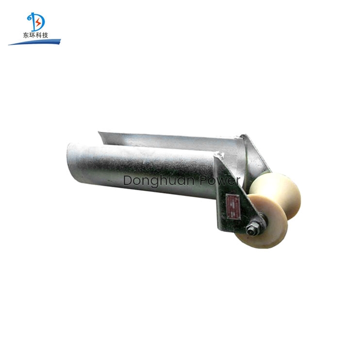
Anti Twist Wire Ropes Manufacturersstringing blocks series
(4) Draw the route of the bridge on the parallel drawing, and indicate the starting point, end point, turning point, branch point and lifting point of the bridge, or the location size and elevation. If the axle side view of the bridge can be drawn, statistics on the materials Will be more precise.
Straight line section: indicate the total length, number of bridge layers, elevation, model and specifications.
Turning point and branch point: indicate the model and specifications of the turning plate used. Lifting section: Indicate the change in elevation, and it can also be represented by a partial large-scale drawing or section drawing.
(5) Bridge support points, such as uprights, support arms or non-standard supports, frame spacing, installation methods, model specifications, elevations, can be agreed to list and explain on the plane, and can also be marked with different sections and single lines Figure or large-scale image representation.
(6) Cable lead-down point location and lead-down method. Generally speaking, a large number of cables can be lead down by vertical bending plate and vertical lead-up rack, and a small amount of cables can be led down by guide plate or guide tube to indicate the lead-down method.
(7) The cable bridge should be 2.2 meters above the ground, the top of the bridge should not be less than 0.3 meters from the ceiling or other obstacles, the width of the bridge should not be less than 0.1 meters, and the filling rate of the cross section of the bridge should not exceed 50%.
(8) When the cables in the cable tray are laid vertically, they should be fixed on the bracket of the cable tray at the upper end of the cable and at intervals of 1.5 meters. When laid horizontally, at the beginning, end, turn and every 3~5 intervals of the cable. Fix it at the meter.
(9) When installed in the suspended ceiling, the opening surface of the slot cover should maintain a vertical clearance of 80 (mm), and the utilization rate of the slot section should not exceed 50%.
(10) The cables laid in the wire trough need not be tied. The cables in the trough should be straight, and the cables in the trough should be straight and not crossed as much as possible. The cables should not overflow the trough. At the place where the cables enter and exit the trough, The turning point should be lashed and fixed. Cables laid in vertical troughs should be fixed on the cable support at intervals of 1.5 meters
(11) When laying wires in horizontal and vertical bridges and vertical wire ducts, the cables should be bound. The 4-pair cables are bundled with 24 cables, and the backbone cables, optical cables and other signal cables of 25 pairs or more should be bundled according to the cable type, cable diameter, and number of cable cores. The lashing spacing should not be greater than 1.5 meters, the buckle spacing should be even, and the tightness should be moderate.
(12) When the bridge is laid horizontally, the support spacing is generally 1.5-3m, and when the bridge is laid vertically, the spacing on the building structure should be less than 2m.
(13) When laying metal trunking, set it up to the rack or hanger under the following conditions: at the joint of the trunking; 3m apart; 0.5m away from the two ports of the trunking; turning.

 English
 Spanish
 +86-574-88852221


